What Is Fast Frequency Response (FFR) in BESS?
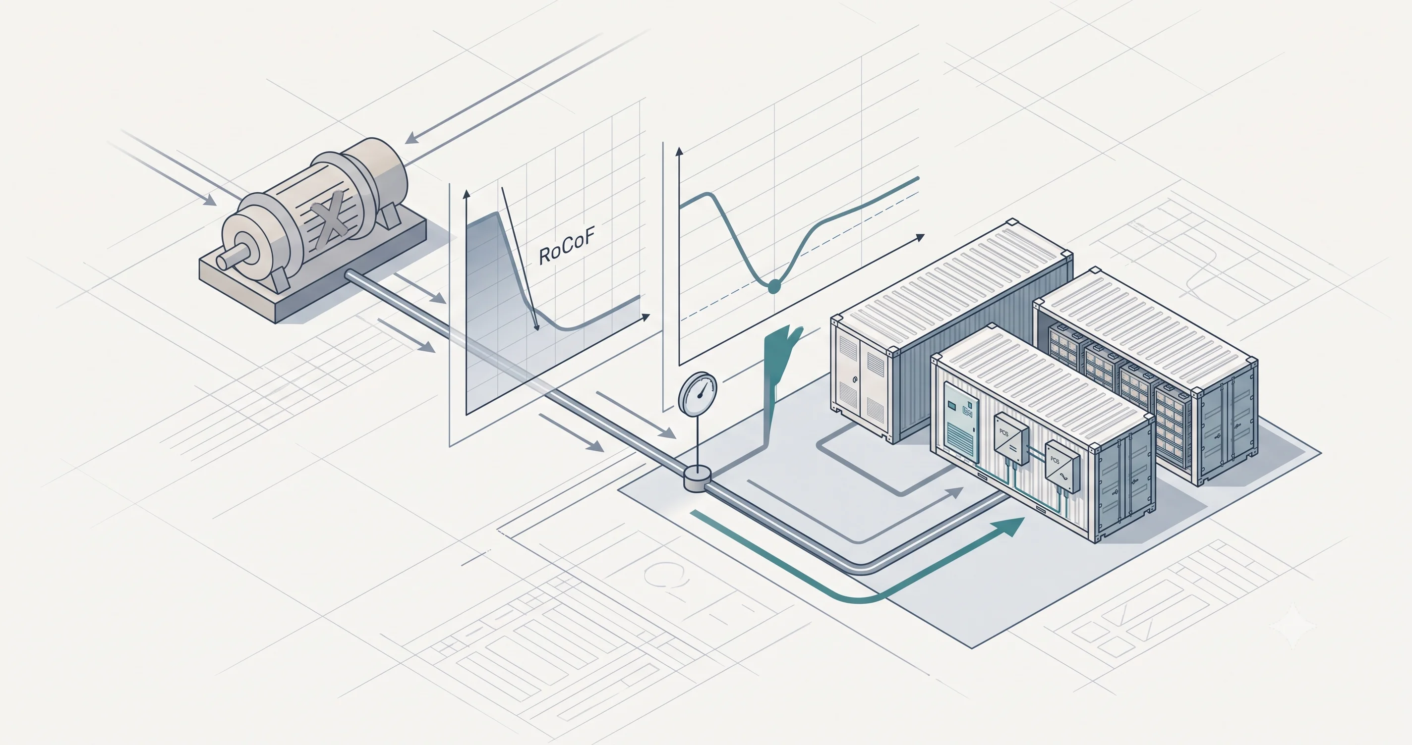
Fast frequency response (FFR) is a balancing service in which a plant injects active power within roughly one second of the grid frequency crossing a preset threshold. The purpose is to arrest a falling frequency before it reaches the first stage of under-frequency load shedding, and the threshold is measured locally at the plant rather than sent as a dispatch instruction.
The service exists because synchronous generation is being displaced. Spinning machines store kinetic energy the system draws on automatically when a large generator trips, and with less of it the frequency falls faster and further after the same disturbance, compressing the window between the trip and load shedding. Grid operators procure FFR to hold the frequency out of that region until the slower reserves activate, paying for a defined MW held available at a defined speed. FCR was designed for a system with large rotating masses and cannot contain the decline on its own.
Fast Frequency Response vs Fast Frequency Reserve
The acronym is used for three different things. Ireland, NERC and AEMO write fast frequency response — a behavior a plant exhibits. The Nordic TSOs write Fast Frequency Reserve — a procured capacity product with its own market and its own prequalification. Great Britain’s legacy Firm Frequency Response was also abbreviated FFR: a slower, tendered product with no relation to sub-second delivery. The same acronym can mean different things in different markets, and the capabilities required to deliver it vary accordingly.
What an FFR Product Specifies
Six parameters define any FFR product.
- Activation threshold or deadband — the frequency at which the service triggers, either a fixed value or a band around 50 Hz (or 60 Hz in North American markets).
- Response time, full activation time, and initiation time — three separate clocks. Initiation time is the delay before output starts moving; response time is when the required output is reached; full activation time runs from the threshold crossing to full output. A headline number means nothing until it names which clock it quotes.
- Droop or step — a response proportional to the size of the deviation, or a fixed injection at a threshold regardless of depth.
- Support duration — seconds in the Nordics, minutes in Great Britain and ERCOT. This parameter alone decides whether a two-hour plant qualifies or only a one-hour plant does.
- Symmetry — up only, or up and down. “FFR is symmetric” is false as a general statement.
- Recovery rules — what the plant may draw to restore its state of charge after an activation, and how quickly it must be armed again.
FFR sits outside the harmonized European balancing framework that covers FCR, aFRR, mFRR and RR. It is procured nationally, against a system need defined by each grid operator’s own inertia conditions, which is why no two FFR products agree on any of the six parameters above.
How a BESS Plant Delivers FFR
Delivery is a latency budget spent stage by stage. A grid-following PCS estimates frequency through a phase-locked loop, and detection alone costs tens to hundreds of milliseconds before any control decision is made. The measurement and the droop or step logic commonly execute locally at the PCS rather than through the power plant controller’s setpoint path, because a dispatch loop routed through the PPC and SCADA can consume most of a sub-second activation envelope on its own.
A typical delivery sequence from frequency event to power at the Point of Interconnection (POI) might look like 50–200 ms for the PLL to estimate the deviation, plus 100–500 ms for the PCS to ramp to rated power. A plant with a fast PLL and a fast PCS can deliver within 250 ms. A plant with a slower PLL and a mid-range PCS is already past 500 ms before transformer and cable delays are counted. Qualification is measured at the POI, on the plant rather than on the converter datasheet.
What remains is state of charge. Every commitment consumes either energy, as a reserved SoC band, or power, as converter headroom: an up-only obligation reserves discharge headroom, a symmetric one reserves both. Recovery power after an activation is capped by the product terms, so the plant cannot recharge at whatever rate suits the trading position.
Why the product suits energy storage is a matter of ramp rate. Thermal plant changes output in percent of rated capacity per minute — roughly 2 to 4% for combined-cycle units, up to about 50% for aeroderivative machines — and governor action does not begin until the deviation clears the governor deadband. A BESS plant ramps from zero to full in under a second, above 100% of rated capacity per second, with no mechanical delay anywhere in the chain.
FFR vs FCR vs Inertia
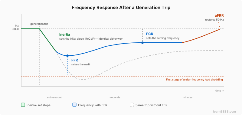
FFR cannot change the initial slope — that is set by the system’s inertia. FFR raises the nadir, FCR sets where the frequency settles, and aFRR restores it to 50 / 60 Hz.
FCR — primary frequency response in non-ENTSO-E naming — is a continuous, proportional droop response on locally measured frequency, with no dispatch signal. Activation timings are synchronous-area specific, but the common requirement is full activation within 30 seconds, sustained for 15 to 20 minutes. FCR determines where the frequency settles; aFRR returns the system to its nominal frequency and mFRR replaces the activated reserves behind it.
FFR is faster, shorter and threshold-driven, and it is dimensioned on the frequency nadir. It exists because at low kinetic energy, FCR activation is not fast enough to hold the frequency through a large disturbance.
Inertia is not a response at all. The initial RoCoF after a trip is set by the size of the disturbance and the system’s kinetic energy, and no measurement-based service can change it. Synchronous machine inertia constants fall in the H = 2–8 s range. A grid-forming BESS plant has no rotating mass, so its virtual H is a configurable control parameter tuned against that range, and it delivers active power proportional to RoCoF without relying on a frequency measurement at all, as set out in the grid-forming and black start guide.
The distinction between synthetic inertia and FFR is measurement, not speed. A grid-forming voltage source responds because of the phase-angle difference between two voltage sources; a grid-following plant delivering FFR has to measure, decide, then inject, which is why its contribution begins after the initial slope has been set. Grid-forming inertia also resists the change without correcting the imbalance: when a 500 MW unit trips, the 500 MW is still missing. Grid-forming is a control mode configured in software at the PCS, FFR and FCR are commercial products, and a plant can carry both.
Mandatory frequency-sensitive-mode obligations sit underneath all of this. Under the European connection requirements a power-generating module has to respond automatically to frequency excursions outside a defined band, unpaid and without any activation signal, whether or not it sells a single MW of FFR.
FFR by Market: ERCOT, Nordics, Ireland, Great Britain and Australia
| Market / operator | Product | Trigger | Full delivery | Sustain | Direction |
|---|---|---|---|---|---|
| ERCOT | FFR as a subset of Responsive Reserve Service | 59.85 Hz | 95–110% of the responsibility within 15 cycles (250 ms) | 15 min or until recall | Up |
| Nordics (Fingrid, Svk, Statnett, Energinet) | Fast Frequency Reserve | 49.7 / 49.6 / 49.5 Hz, provider selects | 1.30 / 1.00 / 0.70 s respectively | ≥5 s where deactivation is ≤20% of FFR capacity per second, otherwise ≥30 s | Up only |
| Ireland (EirGrid / SONI) | DS3 Fast Frequency Response | System event | Fully available within 2 s | Sustainable to 10 s | Charge and discharge |
| Great Britain (NESO) | Dynamic Containment (post-fault) | ±0.015 Hz deadband, activation from ±0.2 Hz | Full delivery at ±0.5 Hz within 1 s | Energy equal to 15 min at full output | Separate high and low services |
| Australia (AEMO) | Very Fast Raise / Lower (R1/L1) FCAS | Contingency event | Enabled amount within 1 s | Until the 6 s fast FCAS takes over | Separate raise and lower markets |
Great Britain’s Dynamic Containment sits alongside Dynamic Moderation, which acts pre-fault to keep the frequency inside the operational band, and Dynamic Regulation, which corrects continuous second-by-second deviation. Only Dynamic Containment is the sub-second post-fault service. Every row in the table is a snapshot of a product under active reform, written against the same six parameters.
IEEE Std 2800-2022 explains why the table disagrees with itself: it separates FFR into categories that are not interchangeable. FFR1 is droop-based and proportional, with a deadband and a step response reaching 90% of steady state in under one second; FFR3 is a unidirectional step at a predefined threshold, with output independent of the depth of the deviation; FFR4 triggers on RoCoF instead. A market buying FFR3 and a market buying FFR1 are procuring different behaviors, so their headline timing numbers were never comparable.
What Goes Wrong in Practice
Grid code compliance is not market qualification. Generic grid code compliance lets a plant connect and export. FCR, FFR and every regional equivalent require separate prequalification — step response, droop response, ramp rate and sustained activation over a defined duration, evidenced with raw measurement data, SCADA logs and signed test reports. It is coordinated by the Route to Market (RTM) provider and runs in parallel with grid compliance testing, but is formally separate from it. Under an EPC contract, prequalification usually sits outside the standard scope and outside the liquidated damages regime, so a plant can pass its performance test and still be unable to bid. In a split-contract model the evidence chain is spread across the PCS supplier, the party responsible for plant-level integration and the RTM provider, and no single party owns the POI-measured response — the gap surfaces at the grid operator’s witness test.
Data resolution is specified years before the first bid. The evidence the grid operator requires — SCADA logging and transient fault recorder data — has to exist at a resolution capable of proving a sub-second response, which makes it an equipment specification decision taken at procurement.
SoC management is the hidden cost. In Great Britain, the dynamic frequency products have on a single high-volatility day driven several equivalent full cycles, and SoC management costs have in some cases consumed the frequency response revenue. Warranties cap lifetime throughput rather than daily use, at an annual average of roughly 1.5 to 2 equivalent full cycles per day, and that number is only comparable across vendors if the underlying C-rate definition matches — cycles are commonly defined at a 0.5C charge and discharge profile.
The question that decides whether FFR is feasible on a project is not whether the PCS can respond in 200 milliseconds. It is: against which grid operator’s product, measured at which point, with the control loop executing where, and with how much state of charge reserved to keep it available. Those four answers belong in the equipment specification and the RTM scope split before financial close, not in a prequalification campaign after COD.