What Is a Ring Main Unit (RMU) in BESS?
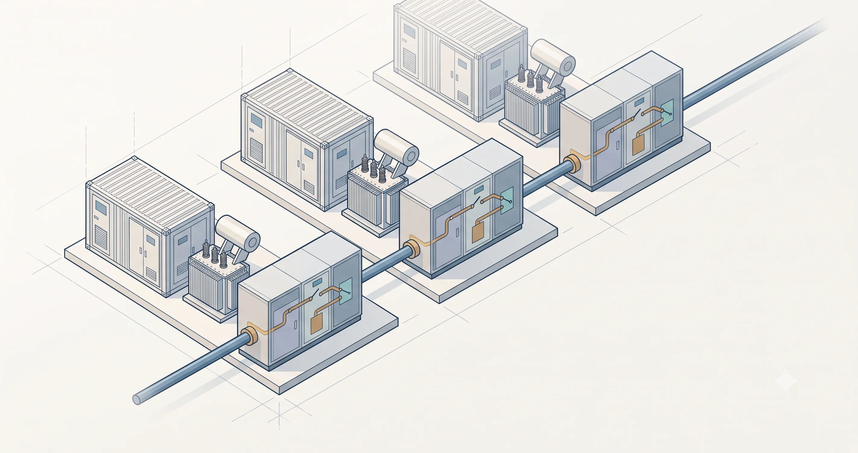
A Ring Main Unit (RMU) is a factory-sealed piece of medium-voltage (MV) switchgear that combines switching, protection, isolation, and earthing in a single enclosure. In utility-scale BESS, there is typically one RMU per section of DC blocks and PCS & MV skid — it is the connection point between the step-up transformer and the MV collection cable that runs to the main substation.
The name is misleading. “Ring main unit” refers to the loop-shaped cable networks the equipment was originally designed for, but in BESS, RMUs are used regardless of whether the collection system is a ring, a daisy-chain, or a radial layout. The RMU is chosen because it consolidates these functions into a single sealed, maintenance-free unit — and because its pass-through design allows multiple units to share a single MV feeder while keeping each one independently isolable.
Where the RMU Sits in a BESS Plant
In a utility-scale BESS plant, the equipment is positioned in a chain. DC blocks feed into a Power Conversion System (PCS), which outputs low-voltage AC to a step-up MV transformer, which is connected to the RMU. The RMU is then connected by the MV collection cable that runs to the main substation.
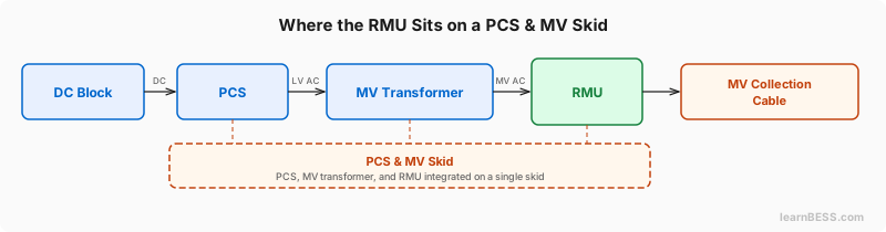 The RMU connects between the MV transformer and the collection cable that runs to the substation.
How this equipment is physically arranged varies. A common configuration is the PCS & MV skid, where the PCS, MV transformer, and RMU are pre-integrated on a single containerized skid. It is also common to have the PCS housed separately, with only the MV transformer and RMU combined on an MV skid. In some designs, all three are installed as separate pieces of equipment with no skid at all.
Functions of a Ring Main Unit
An RMU can include some or all of the following functions, depending on the project’s requirements:
- Load-break switching — connecting or disconnecting sections of the MV cable under normal load conditions.
- Protection — protecting against overcurrent, short-circuit, and earth faults via the transformer feeder.
- Isolation — allowing complete electrical isolation of cable sections or the transformer for maintenance.
- Earthing — grounding conductors after isolation, with mechanical interlocks to prevent earthing while conductors are live.
- Metering — current and voltage transformers can be integrated for energy metering or protection relay inputs.
- Remote control — motorized mechanisms and communication interfaces for SCADA integration.
Which functions are included depends on the project’s protection philosophy, the MV collection topology, and the required level of reliability and serviceability.
MV Collection Topologies
The classic RMU configuration is two ring switch ports plus one transformer feeder — often described as a “2+1” unit. The two ring ports are what distinguish an RMU from a standard circuit breaker panel: the MV cable enters through one port, passes through the unit, and exits through the other. The third port taps off the cable to feed the transformer.
This pass-through design is what enables multiple PCS & MV skids to share a single MV feeder — and it is the reason the RMU appears in most utility-scale BESS collection system designs.
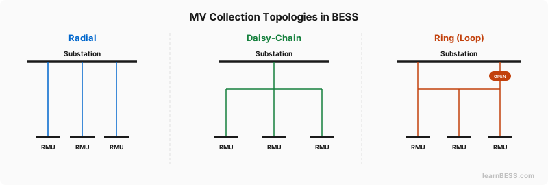 Three MV collection topologies. In a daisy-chain, any skid’s transformer can be isolated via its RMU while the cable continues through to the remaining skids.
Radial. Each skid has its own dedicated MV cable running directly back to the main substation. The pass-through capability of an RMU is not needed in this topology, but an RMU at the skid can still add flexibility for the protection philosophy and local serviceability. The downside of a radial layout is cost: a dedicated cable and substation switchgear panel is needed for every feeder, which on large sites adds up quickly in cabling, trenching, and civil works.
Daisy-chain. A single MV feeder leaves the substation and passes through the RMU at each skid, connecting them in parallel along one cable. This is where the RMU’s pass-through design becomes essential: if a PCS and MV section needs to be taken offline, its transformer feeder is opened while the ring switches remain closed — the MV cable passes straight through the RMU and continues feeding every skid downstream. Each skid can be isolated independently without affecting the others, all on a single feeder.
The limitation is current rating. Each unit on the chain adds to the current flowing through the RMU closest to the substation. The number of units that can share a single daisy-chain feeder depends on the current contribution of each unit and the rated current of the RMU and cable.
Ring (loop). The MV cable leaves the substation, passes through each skid’s RMU in sequence, and returns to the substation — forming a complete loop. During normal operation, one point in the ring is kept open to prevent circulating currents. If a cable section faults, the RMUs at the affected section isolate it, the normally open point closes, and the remaining skids are fed from the other direction. This provides cable-level redundancy on top of the per-skid isolation that the daisy-chain already offers, but requires two feeders at the substation and more cable than a daisy-chain.
Which topology is used depends on the site — the MV voltage level, the current per unit, the RMU and cable ratings, the required level of redundancy, and the cost of civil works.
Main Classifications of RMUs
RMUs are classified primarily by two characteristics: insulation medium and expandability.
Gas-insulated RMUs are the dominant type in BESS. The switching components are sealed inside a gas-filled enclosure, making the unit compact, weatherproof, and virtually maintenance-free for 30+ years. Air-insulated RMUs use ambient air instead. They have a larger footprint and are more exposed to environmental contamination, but offer simpler visual inspection and lower upfront cost.
Non-extensible RMUs are factory-built as a fixed configuration — a 2+1 unit ships as a 2+1 and cannot be modified on-site. Extensible (modular) RMUs consist of individual modules that can be joined together, allowing the configuration to be expanded if the MV collection design evolves.
Gas-insulated RMUs have traditionally used SF6 gas as the insulating medium, but the industry is shifting toward SF6-free alternatives. The EU F-Gas Regulation restricts SF6 in new MV switchgear from 2026 onward, and most major manufacturers now offer SF6-free RMU variants. For new BESS projects in Europe, SF6-free RMUs are increasingly the default specification.
Ratings and Standards
RMUs in BESS are sized to match the MV collection voltage and current. Common voltage classes include 33 kV, 22 kV, and 11 kV, depending on the project design.
The primary design standard is IEC 62271-200, which covers metal-enclosed switchgear for rated voltages above 1 kV up to 52 kV — including insulation levels, short-circuit withstand, and internal arc classification.
Why RMUs Are So Common in Utility-Scale BESS
The RMU is common in utility-scale BESS because it provides a standardized, configurable MV connection point with protection and isolation close to the MV transformer. Its pass-through design also enables flexible cable routing — allowing multiple units to be connected along a single MV feeder in daisy-chain or ring configurations. The same RMU can be specified across different projects, topologies, and site configurations — making it a practical default for most utility-scale BESS designs.