What Is Relay Coordination in BESS?
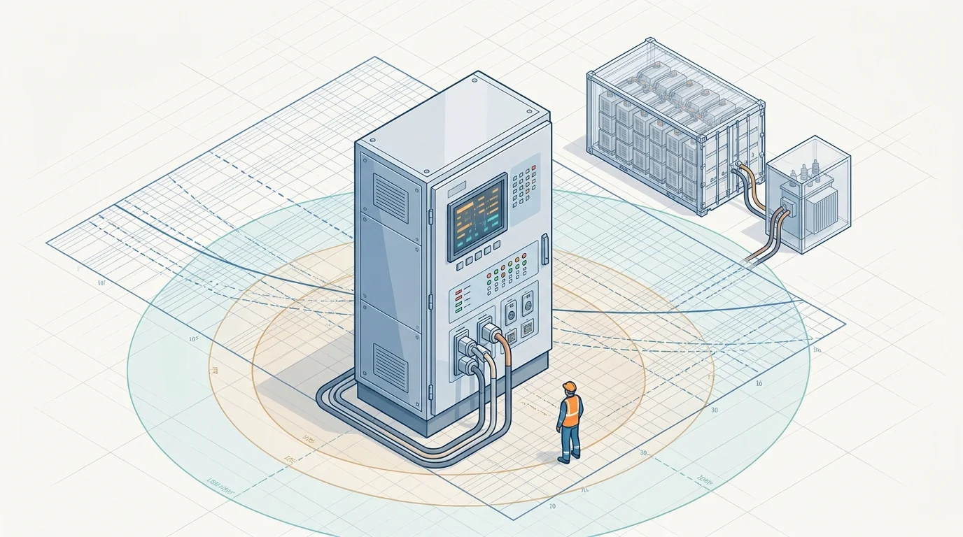
Relay coordination is the principle of ensuring that every piece of protective equipment in a power system trips in the correct sequence when a fault occurs. The equipment electrically closest to the fault trips first, isolating only the affected section while the rest of the plant stays online. This is called selectivity — and achieving it requires a relay coordination study, a systematic engineering analysis that determines the settings for every relay, fuse, and circuit breaker in the system.
In conventional power systems with synchronous generators, this follows well-established procedures. In a BESS plant, three characteristics make it fundamentally different: inverters electronically limit fault current, power flows in both directions, and the plant switches between charging, discharging, and standby — each producing different fault current levels. These differences mean that relay settings designed for conventional generation often fail to protect a BESS plant correctly.
The Relay Coordination Study
A relay coordination study examines the time-current characteristics of every piece of protective equipment in the system — relays, fuses, and circuit breakers — and determines the settings that ensure they trip in the correct sequence.
The central tool is the time-current curve (TCC). A TCC is a log-log graph with current on the horizontal axis and trip time on the vertical axis. Every piece of protective equipment has a characteristic curve showing how fast it trips at a given fault current. When these curves are plotted together, the coordination engineer can verify that downstream equipment trips before upstream equipment, with a coordination time interval (CTI) of 0.2 to 0.4 seconds between them.
The deliverables of a relay coordination study are:
- TCC plots — the coordinated time-current curves for every protective equipment in the system
- Relay settings report — pickup currents, time-dial settings, and instantaneous thresholds for every relay
- Coordination report — the full analysis documenting the study and its findings
Protection Zones in a BESS Plant
A utility-scale BESS plant has multiple voltage levels and equipment types, each requiring its own layer of protection. The relay coordination study ensures these layers work together. The protection zones, from the battery outward:
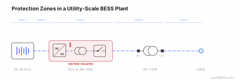 Five protection zones from the DC block to the point of interconnection.
DC block — protection starts at the cell, module, and rack level. DC fuses at the positive and negative terminals of each rack, and the battery management system (BMS) monitoring cell voltage, temperature, and current. Racks are not always DC-coupled, but where they are, the protection within the DC block must account for internal fault paths between racks.
DC block to PCS — the connection between the DC blocks and the power conversion system. Short circuit protection here is critical — the bus must be rated to withstand the combined short circuit current contribution from all racks connected to it. An arc fault on one string can draw current from every other parallel-connected string.
PCS and medium-voltage infrastructure — on the AC side of the PCS, medium-voltage transformers step up the output, and an RMU or MV switchgear provides switching and protection. Transformer differential protection (ANSI 87T) detects internal faults. This is where the individual BESS sections connect into the plant’s MV collection system.
High-voltage substation — from the MV switchgear, the path continues to the secondary side of the high-voltage substation, typically through HV switchgear and then the high-voltage transformer. The HV transformer has differential protection and overcurrent backup on the primary side. Breaker-failure relays ensure that if a primary breaker fails to open, a backup clears the fault.
Point of Interconnection (POI) — the protection at the POI must coordinate with the DSO or TSO’s own protection scheme on the grid side. Transfer-trip signals, synchronism-check relays, and directional elements ensure faults on either side of the boundary are cleared correctly without nuisance tripping on the other side.
Why BESS Is Different
Three characteristics of a BESS plant make relay coordination fundamentally more complex than in conventional generation.
Inverter-limited fault current. Traditional synchronous generators deliver fault current six to ten times their rated output. BESS inverters electronically limit it to often 1.1 to 1.5 times rated current. In some cases, the fault current may not exceed the relay’s pickup threshold at all — the relay never sees the fault.
Bidirectional power flow. Fault current direction reverses depending on whether the plant is charging or discharging. A relay set that coordinates correctly during discharge may misoperate during charging if directionality is not properly addressed.
Multiple operating states. Charging, discharging, standby, and transitional states each produce different fault current levels and system impedances. A setting optimized for maximum output during discharge may leave gaps during low-output standby mode.
The Relay Types
The specific relay types used in a BESS plant depend on the protection philosophy, regional standards, DSO/TSO requirements, and the engineering design of the plant. However, three types commonly appear in relay coordination studies:
| Relay Type | ANSI | Function | BESS Relevance |
|---|---|---|---|
| Overcurrent | 50/51 | Inverse-time and instantaneous overcurrent protection | Challenged by low inverter fault current |
| Differential | 87 | Compares current in vs. out of a protected zone — any difference indicates an internal fault | Does not depend on absolute fault current magnitude |
| Directional overcurrent | 67 | Overcurrent protection that also considers direction of fault current flow | Addresses bidirectional power flow |
Depending on the protection philosophy, BESS plants may also incorporate ground-fault relays for detecting leakage currents and breaker-failure relays as a backup when a primary breaker fails to open.
What Goes Wrong When Coordination Fails
Poor relay coordination does not announce itself until a fault occurs.
- Nuisance tripping — overly sensitive or poorly coordinated settings can trip on normal operating transients such as transformer energization inrush. The plant goes offline when nothing is actually wrong.
- Cascading outages — when upstream protection operates before the downstream equipment closest to the fault, a larger section of the plant is isolated than necessary. Instead of isolating a single BESS section, the outage can cascade upstream and take a significant portion of the plant offline.
- Undetected faults — if relay pickup settings are set above the fault current the inverters can deliver, the fault may persist undetected. In a DC battery system, an uncleared fault can lead to equipment damage and is a fire risk.
Who Does It and When
Relay coordination studies are performed by specialist protection engineers — either through independent power systems consultancies or by developers and EPCs with internal protection engineering capability. The analysis requires specialized software — such as ETAP, DIgSILENT PowerFactory, or SKM PowerTools — to model the system, run short-circuit calculations, and generate TCC plots. The study often begins during the interconnection study phase, when the plant’s electrical design is being finalized and the utility’s protection requirements are known.