What Is Round Trip Efficiency (RTE) in BESS?
Round trip efficiency (RTE) is the ratio of the energy discharged from a BESS plant to the energy required to charge it, expressed as a percentage. It is the single most referenced performance metric in BESS project development.
It is also the most commonly misquoted.
Equipment manufacturers often specify DC block RTE in the range of 94 to 95%. That figure describes the losses inside the DC block alone — mainly driven by the electrochemical losses in the battery cells. It does not include the Power Conversion System (PCS), transformers, cables, and auxiliary systems that sit between the DC block and the Point of Interconnection (POI) with the grid. Once those are included, plant-level RTE drops to the range of 82 to 90%.
DC block RTE is an equipment specification. Plant-level RTE is a business case input. They are not the same number, and confusing one for the other leads to financial models that overestimate revenue from day one.
Why “Round Trip” Matters
The term “round trip” means that energy passes through every piece of equipment in the system twice — once during charging, once during discharging. A transformer with 99% single-path efficiency does not add 1% loss to the overall system. It adds that loss twice: once on the way in, once on the way out. Its round-trip contribution is approximately 2%. The same applies to every cable, every conversion stage, and every connection between the POI and the battery cells.
This is what separates round trip efficiency from single-path efficiency. Single-path efficiency describes losses in one direction. Round trip efficiency accounts for the full charge-discharge cycle — and that distinction changes the math considerably.
Where Losses Occur in a BESS Plant
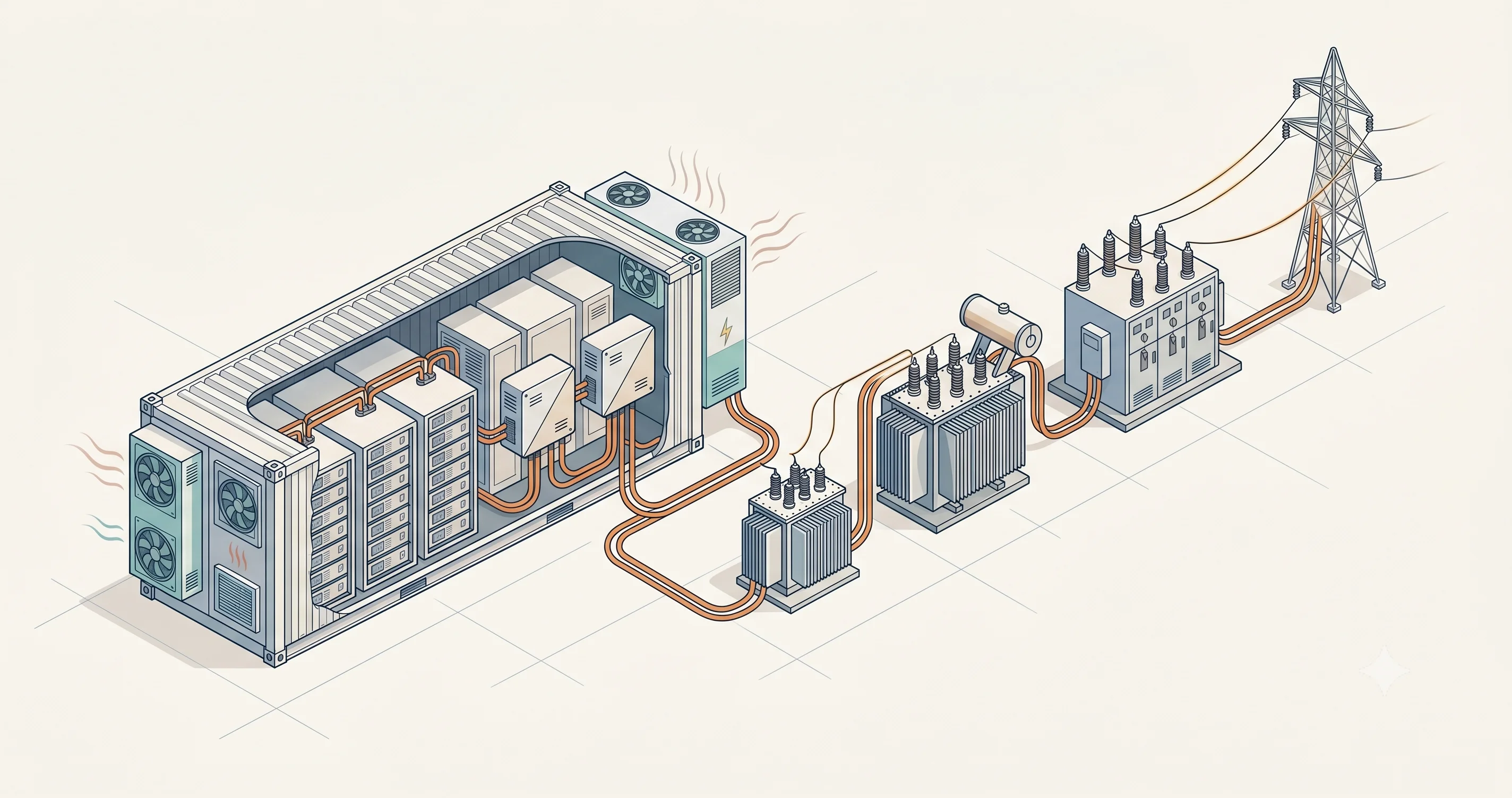
A BESS plant contains multiple pieces of equipment between the POI and the battery cells. Each one introduces electrical losses, and those losses are applied in both directions.
DC Block
The DC block — containing the battery cells — is the largest single contributor to RTE losses. Equipment manufacturers specify DC block RTE in the range of 94 to 95%, covering both the electrochemical losses in the cells and the electrical losses in internal equipment.
This figure excludes auxiliary power consumption — a point that matters significantly at the plant level.
Power Conversion System (PCS)
The PCS converts between DC and AC power during every charge and discharge cycle. It is the interface between the DC block and the AC side of the plant. Single-path efficiency for a modern PCS is in the range of 98 to 99%, with losses driven primarily by the switching and conduction losses in the power electronics. Like every other component in the chain, these losses are applied twice for round trip.
Transformers
A BESS plant commonly passes through two transformers — one stepping between low voltage and medium voltage, and one between medium voltage and high voltage — though the number varies depending on the grid connection voltage and plant design. Each transformer introduces active power losses during operation and no-load losses even when the plant is idle. Additional impedance and reactive power losses apply depending on operating conditions.
A single-path efficiency of around 99% per transformer is representative for modern equipment.
Cables
DC cables, low-voltage AC cables, medium-voltage AC cables, and high-voltage AC cables connect each piece of equipment. Each cable segment adds losses that depend on the cable type, cross-section, length, and current. Cable losses can be significant depending on the distances between equipment and the distance to the POI. They accumulate across the system and are applied in both directions.
Calculating Plant-Level RTE
The overall plant RTE is the product of the round-trip efficiency of every component in the system.
For equipment specified with single-path efficiency, the round-trip value is the single-path efficiency squared — because energy passes through that equipment twice.
The following example uses representative values for a utility-scale BESS plant.
| Equipment | Single-Path Efficiency | Round-Trip Efficiency |
|---|---|---|
| DC block | — | 94.00% |
| DC cables | 99.90% | 99.80% |
| PCS | 98.50% | 97.02% |
| LV AC cables | 99.90% | 99.80% |
| Transformer (MV/LV) | 99.00% | 98.01% |
| MV AC cables | 99.80% | 99.60% |
| Transformer (HV/MV) | 99.00% | 98.01% |
| HV AC cables | 99.80% | 99.60% |
Multiplying all round-trip efficiencies together:
94.00% × 99.80% × 97.02% × 99.80% × 98.01% × 99.60% × 98.01% × 99.60% = ~87%
For every 100 MWh charged from the grid, approximately 87 MWh can be delivered back to the POI. The remaining 13 MWh is lost to heat and electrical resistance across the equipment chain.
This is the equipment-level RTE of the BESS plant. It already represents a significant drop from the DC block’s 94%. But it still excludes one major variable.
Auxiliary Power: What the Datasheet Excludes
The DC block RTE of 94 to 95% does not include the power consumed by the DC block’s own auxiliary systems — primarily HVAC, cooling fans, and battery management electronics. This consumption is not fixed. It varies with the plant’s load profile, discharge power, cycling frequency, ambient temperature, and wind conditions. A plant cycling aggressively in 40°C ambient temperatures will consume far more auxiliary power than one operating conservatively in a temperate climate.
For the DC block alone, auxiliary power consumption can range from 1.5 to 4% of throughput depending on operating conditions. The remaining plant-level auxiliary systems — the power plant controller (PPC), SCADA, monitoring equipment, switchgear, and lighting — add roughly 1% more.
Adding auxiliary power to the example above:
| Scenario | Auxiliary Load | Plant-Level RTE |
|---|---|---|
| Equipment only (no auxiliary) | — | ~87% |
| Low auxiliary load | ~2.5% | ~84% |
| High auxiliary load | ~5% | ~82% |
The DC block datasheet says 94%. The plant at the POI delivers 82 to 84%. That gap — ten to twelve percentage points — is made up of losses that are either excluded from the equipment specification or too variable to pin down at the design stage. In many cases, the actual auxiliary power consumption only becomes fully visible once the plant is operating and the trading performance can be measured against the financial model.
This is why auxiliary power modeling deserves as much attention as the equipment selection itself. Underestimating it does not change the physics. It changes the revenue forecast.
What This Means for the Business Case
For a BESS plant operating in energy arbitrage, RTE determines the effective cost of every megawatt-hour sold back to the grid. The lower the plant-level RTE, the more energy must be purchased to deliver each unit.
Consider a plant buying energy at 50 EUR/MWh and selling at 100 EUR/MWh:
| Plant-Level RTE | Effective Cost per MWh Sold | Gross Margin |
|---|---|---|
| ~87% (equipment only) | 57.5 EUR/MWh | 42.5 EUR/MWh |
| ~84% (low auxiliary) | 59.5 EUR/MWh | 40.5 EUR/MWh |
| ~82% (high auxiliary) | 61.0 EUR/MWh | 39.0 EUR/MWh |
The gap between equipment-only RTE and high auxiliary load costs approximately 3.5 EUR on every megawatt-hour traded. On a plant cycling daily, that difference compounds into a significant annual revenue shortfall against any financial model that did not account for realistic auxiliary power consumption.